The Equation Controlled Voltage and Current Source:
What is it?
The Equation Control Voltage Source generates a voltage that
is determined by a user specified equation. In a similar way, the
Equation Controlled Current Source generates a current. In both
components, the equation is a function of the voltage at two sets
of inputs. The example below will explain this in greater detail.
What is it good for?
We use an Equation Controlled Voltage Source to compare our past assets with our present assets
for payment of taxes.
An Equation Controlled Current Source is used to transfer our funds to the government for tax payment
based on the current tax rate.
The fact that the user can specify most any equation makes this component
very useful.

Tell me more!
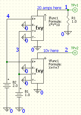
At the left is shown a test circuit to illustrate the Equation Controlled
Voltage and Current Source. The fxy component at the top generates a current
and the fxy component at the bottom generates a voltage. Both of these
components allow a user specified equation to control the output current or
voltage. The fxy at the top generates a current defined by the equation X*Y*10.
The fxy at the bottom generates a voltage defined by the equation X+Y+7.
The value of X in these equations is the difference voltage (x+) minus (x-)
at the control input. The Y is the difference voltage (y+) minus (y-). In this example, both
values for X are 2 volts and both values for Y are 1 volt. In this case the
current source generates 20 amps. The resistor R1 is used to provide a current
path to ground and also generates a voltage that is proportional to the current
for the TPv1 test point. The circuit connection names (also called circuit nodes)
are the large blue numbers shown on the schematic.
SPICE Description Format:
The schematic capture program automatically generated the following circuit description:
R.R1 1 0 1.0
V.B2 4 0 2.0
V.B1 3 0 1.0
B.Ifunc1 0 1 I=(v(4)-v(0))*(v(3)-v(0))*10
B.Vfunc1 2 0 V=(v(4)-v(0))+(v(3)-v(0))+7
The first line defines resistor R1 connected between circuit node 1 and ground (node 0).
The second line describes the battery with a voltage of 2.0 volts between node 4 and ground.
The third line is the second battery with a voltage of 1.0 volt connected between node 3 and node 0.
The fourth line describes the current source connected between node 0 and node 1.
The fifth line is the voltage source between node 2 and ground.
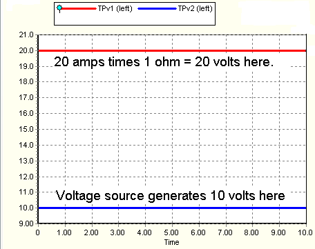
The simulation result for this test circuit is:

Back to the components page

