The Voltage Controlled Switch:
What is it?
This switch senses voltage at the switch control inputs. If this voltage is above
a voltage threshold, the switch closes. If the voltage is below the threshold, the
switch is open.
What is it good for?
A switch is often useful to set the initial starting voltage on a capacitor. For example,
the switch may be closed at the start of the simulation to place 10 volts on a capacitor.
When the simulation gets under way, the switch turns off having performed its function.
Another use of a switch is to sample a voltage that represents our earnings at a moment
in time. This voltage will be placed on a capacitor where it remains unchanged. At a later moment
in time, another switch can sample our current earnings. Now we can compare our past
earnings to our current earnings and decide how much taxes we owe.
We use several switches in our model that calculates profit and pays taxes.

Tell me more!
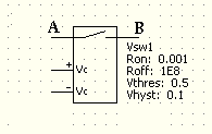
At the left is shown the electrical symbol for a Voltage Controlled Switch. The
voltage between the +Vc and -Vc inputs determine whether the switch is open or closed.
Four parameters are used to define the characteristics of the switch:
Ron, Roff, Vthres and Vhyst.
Ron is the resistance of switch between point A and point B when it is closed. This is usually set
to a small value such as 0.001 ohms.
Roff is the resistance of switch between point A and point B when it is open. This is usually set to
a large value such as 1E8 (100,000,000.0) ohms.
Vthres is the threshold voltage at which the switch changes on/off position. When +Vc minus -Vc reaches
0.5 volts in this example, the switch is at threshold.
Vhyst is called the hysteresis voltage. This is a voltage "push" beyond the threshold voltage (Vthres) needed
to actually throw the switch. If the voltage between the +Vc and -Vc terminals is sitting exactly at the
threshold voltage, then a small amount of random noise could cause the switch to turn on and off rapidly.
The additional hysteresis voltage required to throw the switch helps to eliminate this switch chatter.
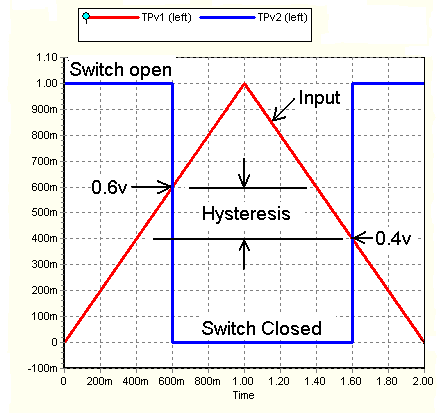
In this example Vhyst is set at 0.1 volts. If the voltage between +Vc and -Vc is greater than the threshold voltage
plus the hysteresis voltage (0.6v), then the switch will be closed. If this voltage is less than the threshold voltage
minus the hysteresis voltage (0.4v), then the switch will be open. Thus the switch turn on voltage is 0.6 volts
or more and the turn off voltage is 0.4 volts or less. If the control voltage is greater than 0.4 volts and
less than 0.6 volts, then the switch will not change.
SPICE Description Format for the Voltage Controlled Switch:
The SPICE description format for the Voltage Controlled Switch pictured above is:
SVsw1 A B +control -control Sw_model_name
.model Sw_model_name SW(RON=0.001
+ ROFF=1E8 VT=O.5V VH=0.01V)
The first character in the switch description must be an "S". This tells the SPICE program that this circuit element is a
switch. SVsw1 is the name of this particular switch.
The switch connections are listed first followed by the plus and minus control connections. The final listing in this line
is the model name of the switch. The next line defines the switch parameters for this switch model name.
The "+" character at the start of the third line tells the SPICE program that this line is a continuation
of the previous line. This model statement should appear only one time in the circuit description. Other switches
in this circuit description can share this same switch model.
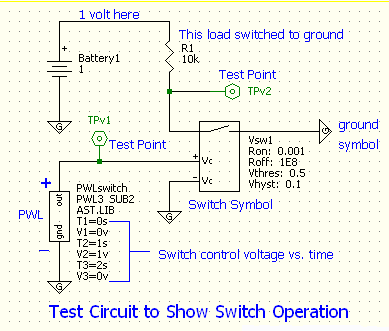
A test circuit to illustrate switch operation is:

The simulation result is:

Back to the components page


